Sometimes you want to integrate some of the old technology into a smart home environment, but there is not the right sensor available. So why not build one yourself or modify an existing one into a DIY Zigbee logic sensor? That’s what happened to me a while back when I was looking for a way to monitor the doorbell. In some rooms it is not easy to hear and integration into an existing smart home environment offers some additional possibilities.
Since my devices mainly come from Xiaomi / Mijia, the sensor should of course fit (Zigbee output). A first try with a Mijia vibration sensor was OK, but not very reliable. Therefore, I have built a sensor, which I can switch directly to the AC voltage parallel to the bell and it reports the state to Mi Home. I think there are many other uses for this easy and cheap sensor.
Guest post by Volkmar L. (Antenne519)
Contents
What is needed?
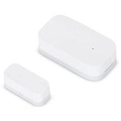
- Door/Window sensor from Xiaomi / Mijia (MCCGQ01LM)
- Optocoupler, preferably with AC input e.g. a SHARP PC81411NTP (I purchased it very cheap at Pollin Elektronik)
- a SMD resistor for current limiting (depending on the voltage and current requirements of the coupler, for example 10 KOhm)
- Thin 2-core wire
Assembly of the DIY Zigbee Logic Sensor
The door sensor MCCGQ01LM has a reed contact, which is normally operated by the supplied magnet.
Total Time: 30 minutes
I installed an optocoupler parallel to this contact, which allows me to monitor any sources for ON / Off.
Conveniently, the MCCGQ01LM already has two pads at the appropriate location, which are connected to the reed contact. The optocoupler ensures potential separation.
After opening the sensor, the pads can be seen on the free space of the board. These are labeled GND (Ground / -) and D+.
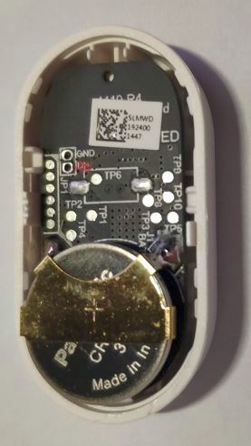
Positive pole D+ marked in red
These pads are used to connect the output of the optocoupler (emitter GND, collector +).
A component in a DIL housing with “pins” could be plugged directly into the pads, with the SMD type I used, I have slightly modified the pins and connected them with small wires to the PCB. 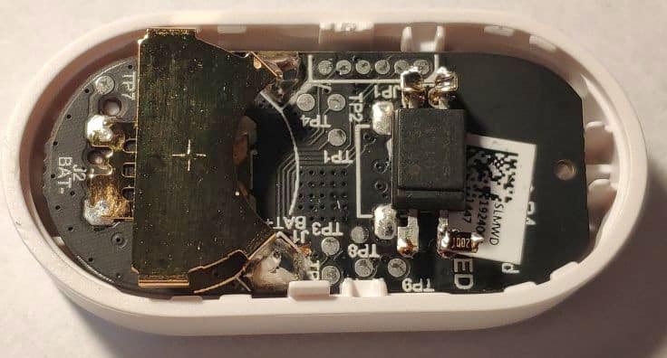
The optocoupler with the parallel to the circuit board bent terminals was fixed with a dab of glue.
You must be careful that the component does not protrude too far over the small sticker with QR code, otherwise the round support of the lid will find no place.
(Note the round impression of the foot, this space must remain free, so install the opto-coupler a bit at an angle.)
The two opposite pins are the input of the optocoupler. By using an AC model with 2 LEDs, the polarity does not matter later.
Since the SHARP PC81411 is also a “low power” model, it needs very little current to trip. With an input level of 9..12V AC to be monitored I have therefore chosen a 10 KOhm resistor to limit the current and soldered it directly to one of the pins.
However, the input voltage should not exceed about 48..60V, otherwise you must better isolate everything and choose a resistor capable for a higher voltage.
A 2-core cable leads the input out of the housing through a drilled hole.
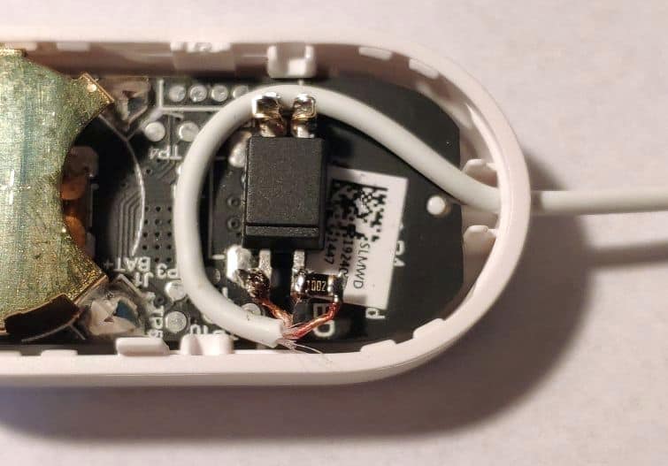
The finished sensor can now be put back together, the battery is inserted and the lid closed.
The cable can then be fit with a plug or soldered directly to the source. The modified unit can still be used as originally intended (operated by the magnet) because the reed contact is still in place and will work as before the mod. 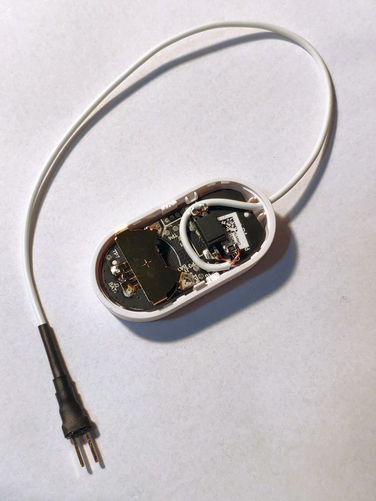
Results / Conclusion
Due to the built-in resistor, the Zigbee logic sensor can be directly connected to the doorbell (about 9V AC). When a voltage is applied (someone operates the bell) the opto-coupler turns the sensor on and it can e.g. send the signal to a Mijia Gateway as a ringtone or report it to your smartphone. The Mi Home app also creates logs about the switching process.
I have used the Xiaomi / Mijia door contact sensor (MCCGQ01LM) as it is compatible with probably all Mijia gateways (and is also included in the Xiaomi sensor kit sold in Europe)
The comparable sensor from Aqara may also be suitable. Since the door contact sensor used is very cheap and uses the Zigbee protocol, I could imagine that there are a variety of other uses for my modified version. Whenever a logic level (voltage on / off) is to be monitored, it is applicable.
Next project planned: Connect the DIY sensor to a 230V AC 20A current sensor module to monitor the washing machine…
This is a guest post by Volkmar L (nickname Antenne519). He approached us about sharing this project with the community and we are very glad he wanted to share his experiences with us. Thank you very much for this contribution! If you also want to share an interesting home automation project with us, feel free to drop us a message.


